MicroLink Technology

MicroLink Data Centers Technology dossier

MicroLink's
Technology
Development

Where we are developing intellectual property
and first to market solutions.
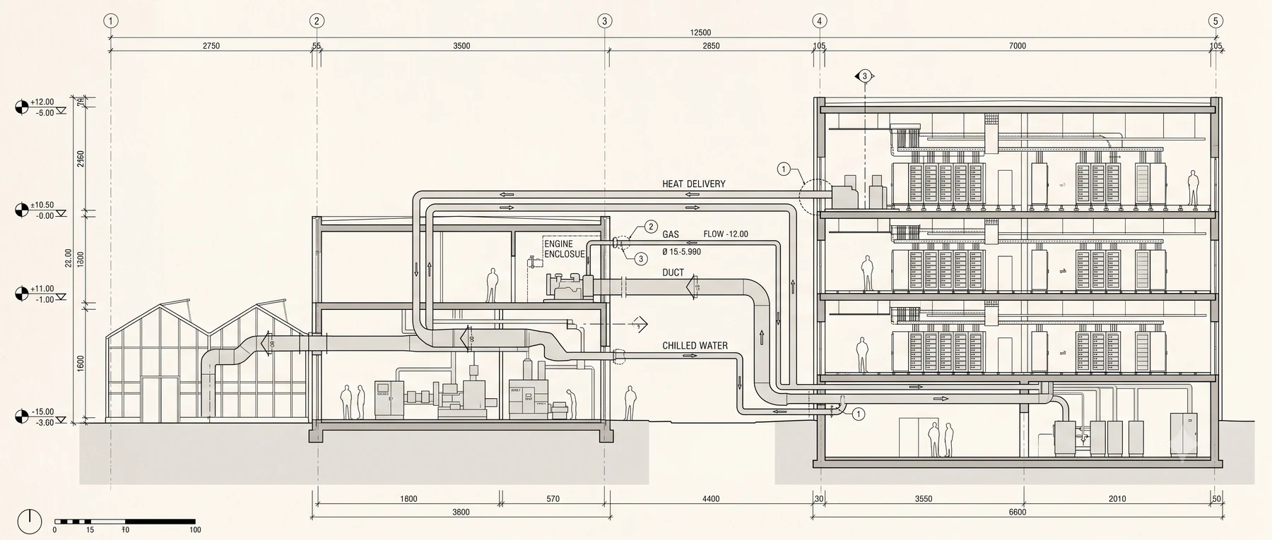
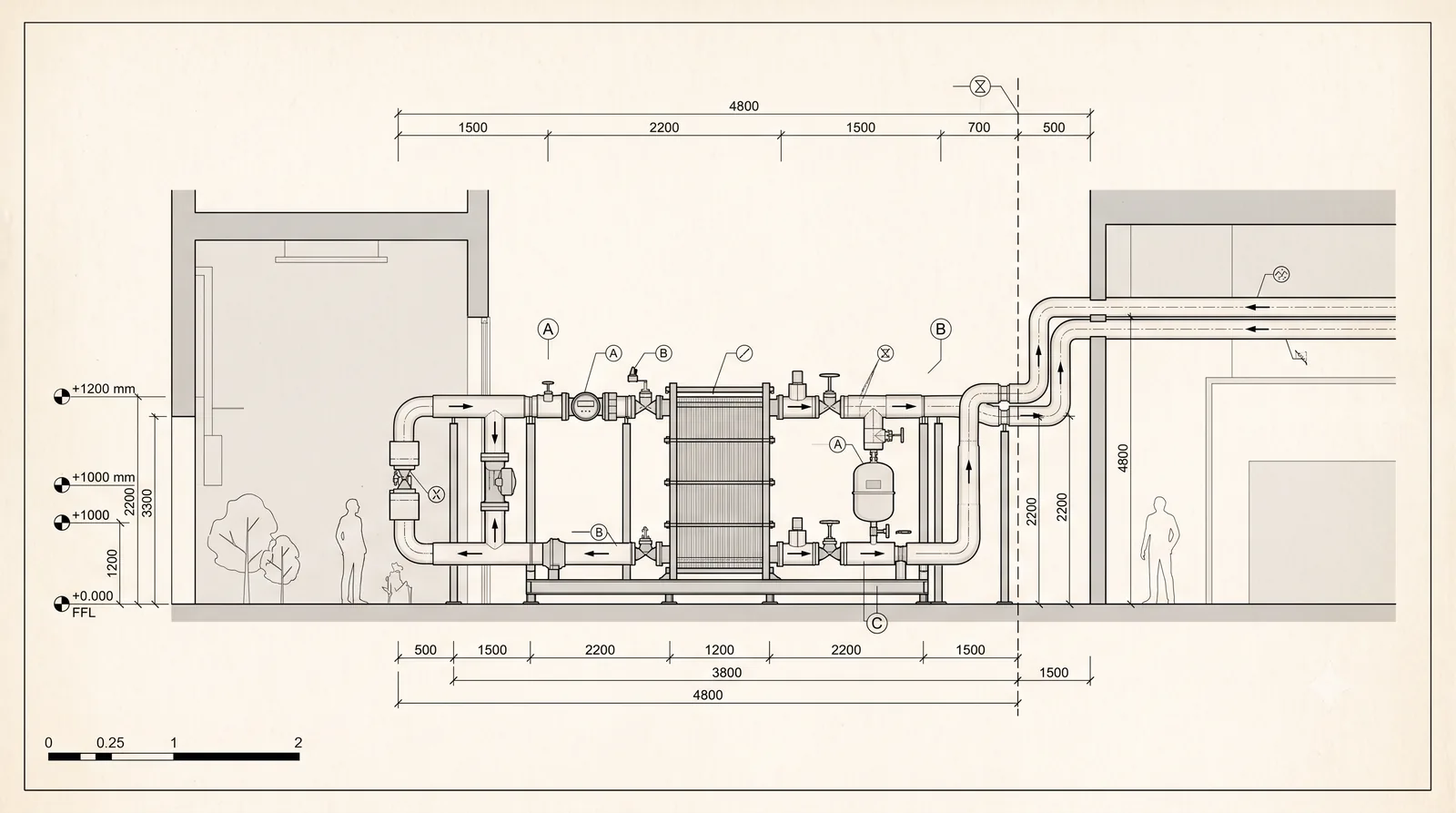
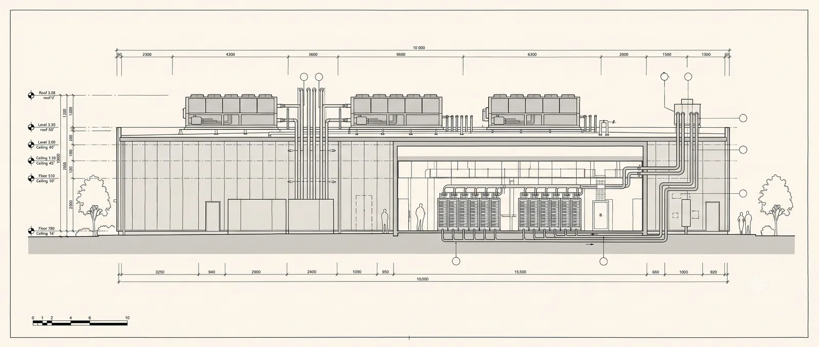
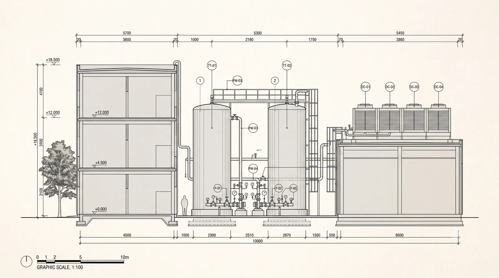
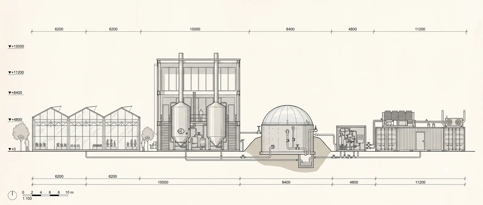
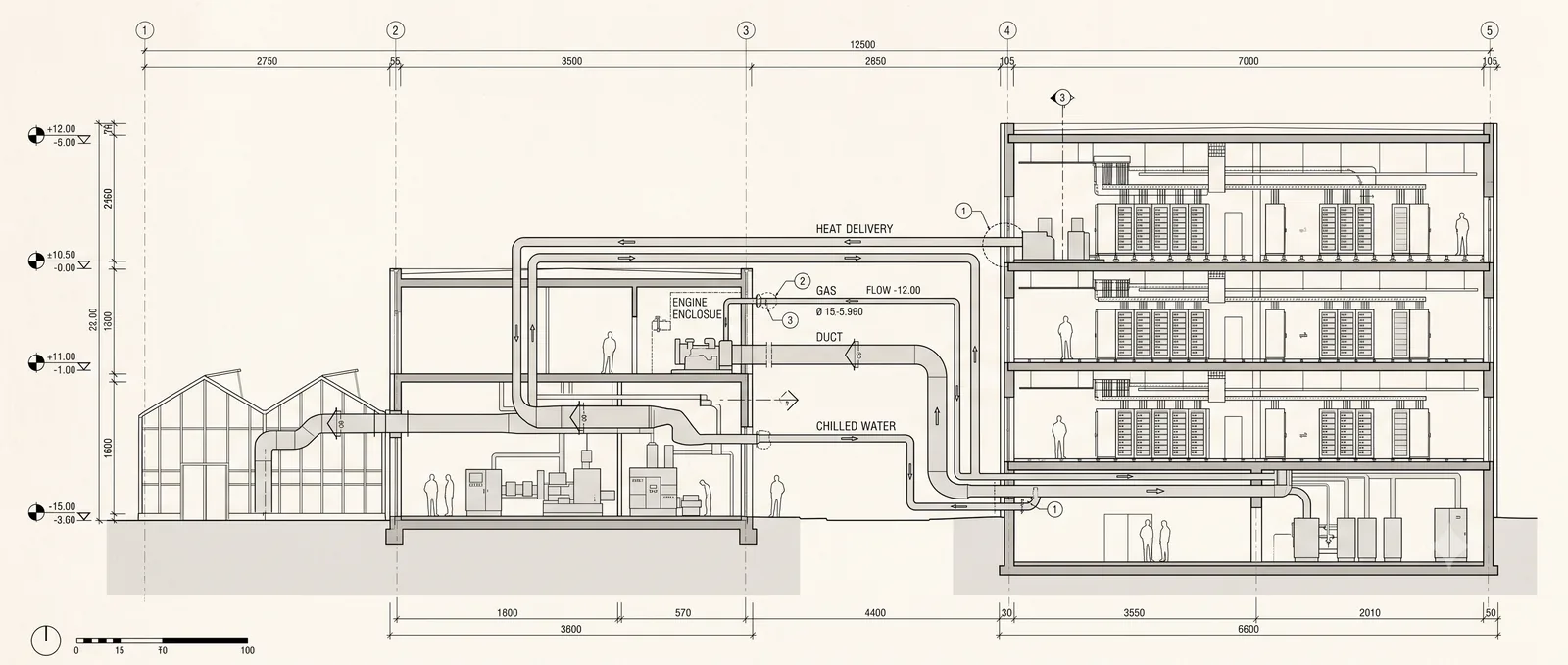
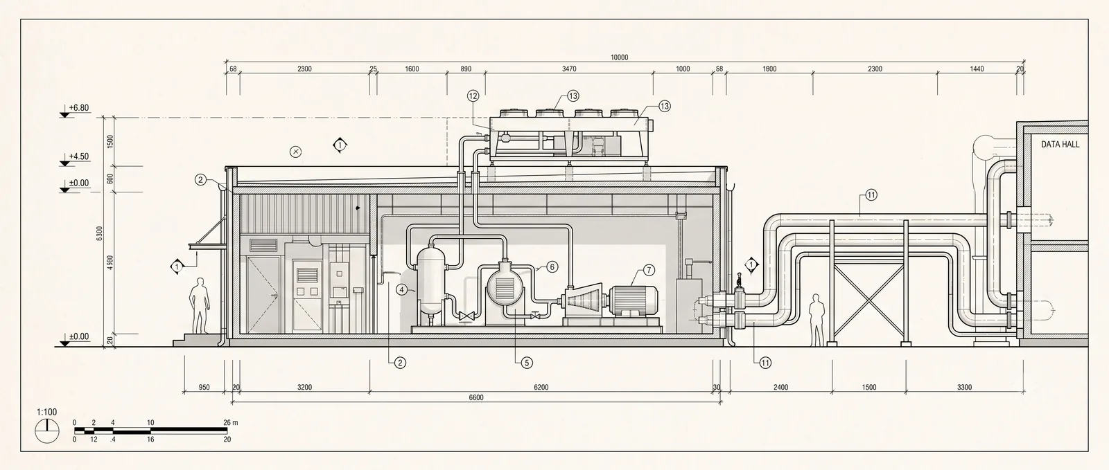
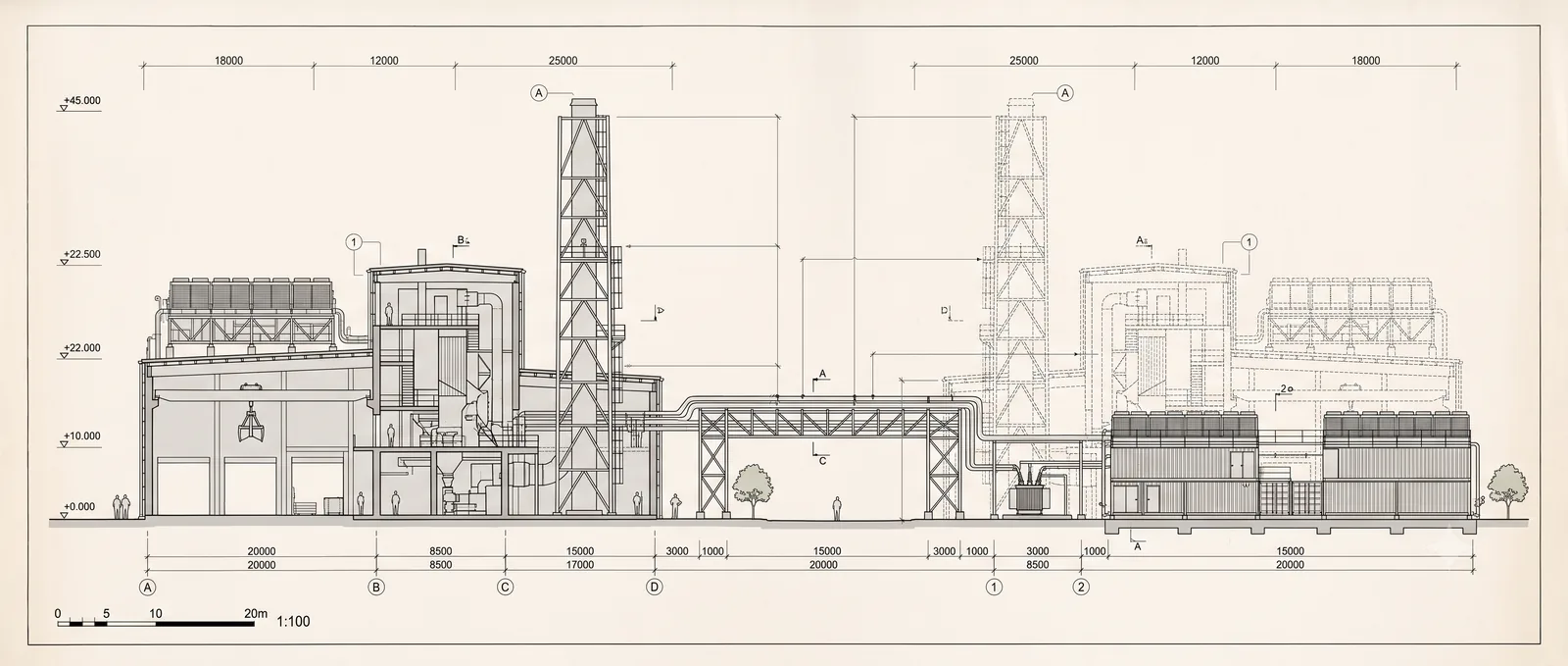
Elevation drawing of a MicroLink host campus: greenhouse range, energy centre and data hall

Heat walks from the rack to the host

Every MicroLink deployment moves heat along the same path: the server loop through exchanger A, across the recovery loop to exchanger B, and into the host partner's process. The cooler on the return rail carries whatever the host partner does not take, hour by hour.

L1 SERVER LOOP L3 HOST DELIVERY EXCH A EXCH B SERVER RACK COOLER DIGESTER 70 °C (158 °F) 35 °C (95 °F) 55 °C (131 °F) 10 °C (50 °F)
Supply side, cool loopReturn side, recovered heat

Who we are

MicroLink Data Centers builds high density, liquid cooled compute inside industrial host partner facilities: places that already hold the power and already buy the heat. Almost every watt a chip draws leaves the silicon as heat. Everyone else throws it away. We treat it as a second product.

Placeholder copy: founding, team, entity structure, footprint to date.

IMAGE PLACEHOLDER: deployment photo

What we do

We develop and operate compute across three scales on one shared stack: a 50 kW edge block, a 1.25 MW pod, and campuses from 10 MW up to 1 GW. No other company is developing a continuous range across these applications. Every scale runs the same software, the same thermal philosophy and the same dry cooler backed architecture, so what is proven at one scale carries to the next.

How we do it

We standardise the hardware and develop the layer above it. Cooling distribution, power modules and IT hardware are standardised with Vertiv and other leading manufacturers. MicroLink's own development, and its IP, sits in control, monitoring and management software, in system and solution design for compute inside industrial sites, in 800 V DC power, and in the systems that couple generation optimisation and heat recovery to compute. Delivered performance is reported as ERE alongside PUE, from live metering.

MICROLINK DEVELOPED Control, monitoring and management software System and solution design 800 V DC power Generation and heat STANDARDISED WITH PARTNERS Cooling plant Power modules IT hardware Vertiv and other leading manufacturers

Where we sit in the ecosystem

UPSTREAM

Manufacturers

Vertiv and other leading manufacturers supply standardised hardware against MicroLink reference designs.

ALONGSIDE

Host partners

Industrial facilities, district energy networks and utilities that hold power and buy delivered heat.

DOWNSTREAM

Compute offtake

Placeholder: colocation, cloud and AI capacity offtake across the three scales.

Team

Nick Searra

LinkedIn
CEO, Co Founder

Two decades of EMEA data center and power infrastructure development.

Shane Pather

LinkedIn
CTO

Controls engineer, commissioned Europe's largest heat recovery data centers.

Dane Harvey

LinkedIn
CFO

Thirteen years with GE, ending as Global Cash FP&A Leader in Boston.

Jamie Brown

LinkedIn
General Counsel

Data center and real estate counsel, Harvard Law, formerly Meta and Fifth Space.

Carla Trippe

LinkedIn
Head of Operations and Impact

Fourteen years of impact and operations, USAID, Gates Foundation, United Nations.

Andrew Thomas

LinkedIn
Chief Commercial Officer

Energy storage executive, co founder and president of Acculon Energy, Ohio.

Jeff Svedahl

LinkedIn
CEO, MicroLink Edge

Twenty five years of global procurement for Choice Hotels, Radisson and Target.

Heath Andersen

LinkedIn
Data Center Design Advisor

Twenty five years of data center design across Australia, the UK and the Middle East.

Sancha Olivier

LinkedIn
Strategic Advisor

Data center architect and senior project manager, mission critical data center design.

David Hassler

LinkedIn
Head of Sales and Customer

Twenty five years in capacity planning, seventeen at Akamai, now at Vultr.

Deniz Akgul

LinkedIn
Capital and Investment Advisor

Structured finance advisor, Houlihan Lokey and Brevan Howard, founder of White Rose Capital.

Submitted IP

MicroLink's first patent family is filed and pending. The strategy is a two patent fence: a narrow filing that proves the system in its first embodiment, and a broad filing that covers the industrial symbiosis category across host types. IP is held in a dedicated IP holding entity within the group structure.

ReferenceTitleScopeStatus
ML 001Wastewater deploymentNarrow filing covering the first embodiment at a wastewater treatment host, establishing the earliest priority dateFiled, patent pending
ML-IND-001Industrial Symbiosis Data Center SystemBroad category filing: high density liquid cooled compute co located with an industrial host, waste heat captured, conditioned and delivered as a controlled thermal input, with thermal isolation, demand responsive control and closed loop energy cyclingSubmitted, patent pending, April 2026 priority

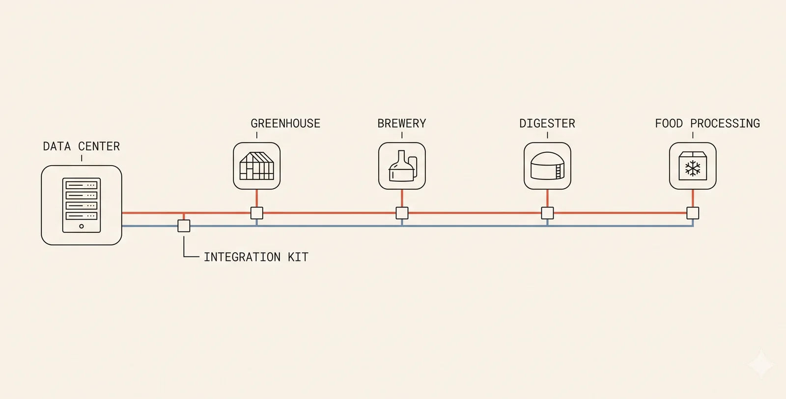
Four embodiments in the broad filing

WASTEWATER TREATMENT

Digester heating

Heat demand 35 to 55°C (95 to 131°F). Loop closure: biogas to supplementary power.

BREWERY

Hot water and cleaning

Heat demand 65 to 85°C (149 to 185°F). Loop closure: fermentation CO2 to transcritical cooling.

CONTROLLED ENVIRONMENT AGRICULTURE

Climate and enrichment

Heat demand 18 to 28°C (64 to 82°F) plus CO2 enrichment. Loop closure: CO2 and humidity to plant growth.

FOOD PROCESSING AND COLD CHAIN

Pasteurisation and cleaning

Heat demand 60 to 90°C (140 to 194°F). Loop closure: refrigeration condenser coupled to data center cooling.

Filing references and scope summarised from the provisional application overview. Detailed claims are not published here.

Read next

Solutions

Technology register

The solutions under development in heat reuse, optimisation and generation.

Open solutions
Projects

Where it is proven

Twelve portfolio sites and the technologies each one carries.

Open projects
Reference

Partners and research

Manufacturers we standardise with, technologies we work with, and research to date.

Open reference

Solutions Technology under development

Three families, one stack

Eighteen solutions across three families, every one developed across the full range from the 50 kW edge block to the 1 GW campus. Open any block for what it is, what is new, and where the IP sits.

Recovery

RC 01

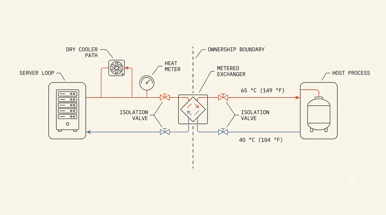
Metered heat delivery interface

One metered exchanger between MicroLink plant and the host partner's systems: process hot water, digesters, district heat, greenhouses. The commercial and physical boundary in a single engineered product.

Solution detail
RC 02

High grade return water

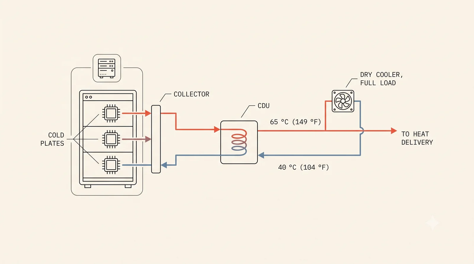
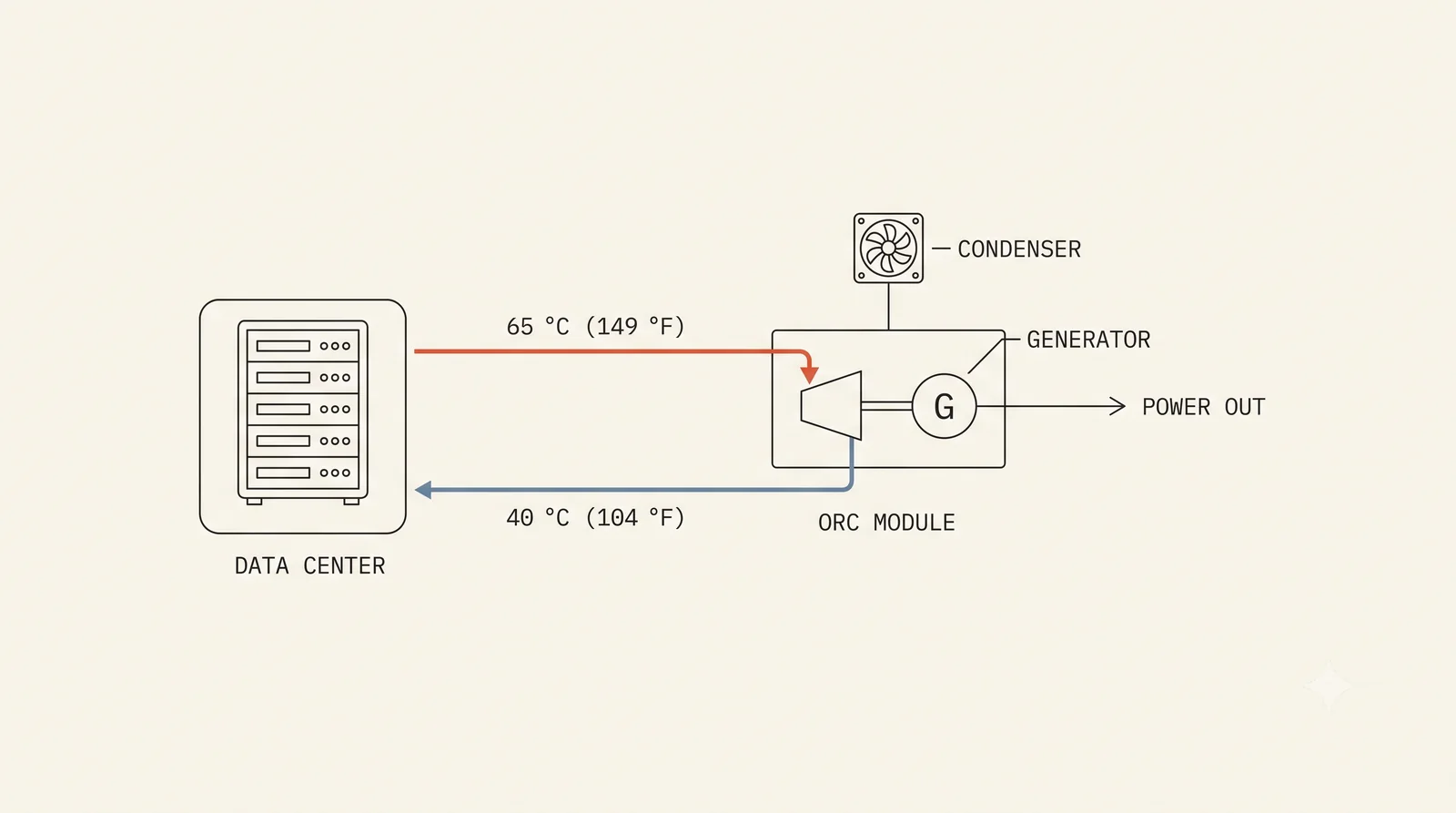
Direct to chip liquid cooling engineered from the first decision for recovery, returning water at 40 to 65°C (104 to 149°F) matched to real industrial demand.

Solution detail
RC 03

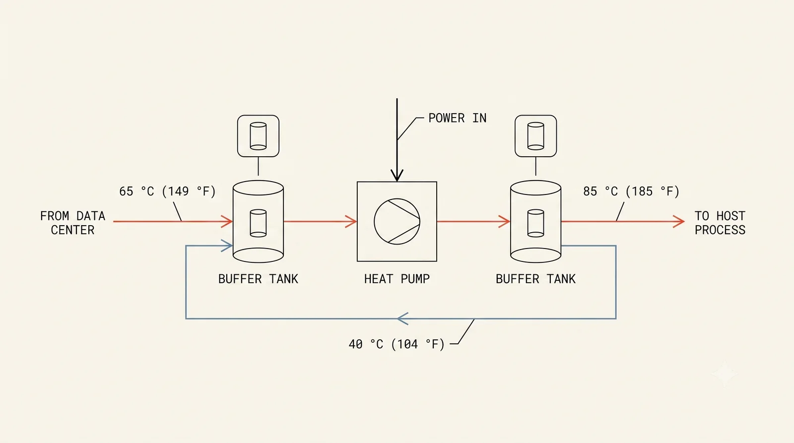
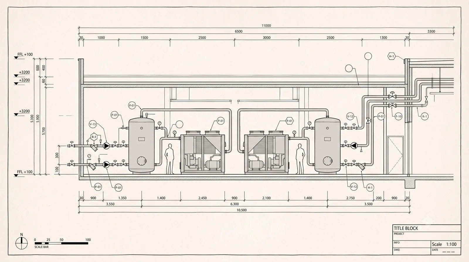
Heat pump temperature boosting

Conditioning stage heat pumps lift return water to the temperature the host process actually needs, from digester duty at 35 to 55°C (95 to 131°F) up to cleaning and pasteurisation duty at 60 to 90°C (140 to 194°F).

Solution detail
RC 04

Demand matching and storage

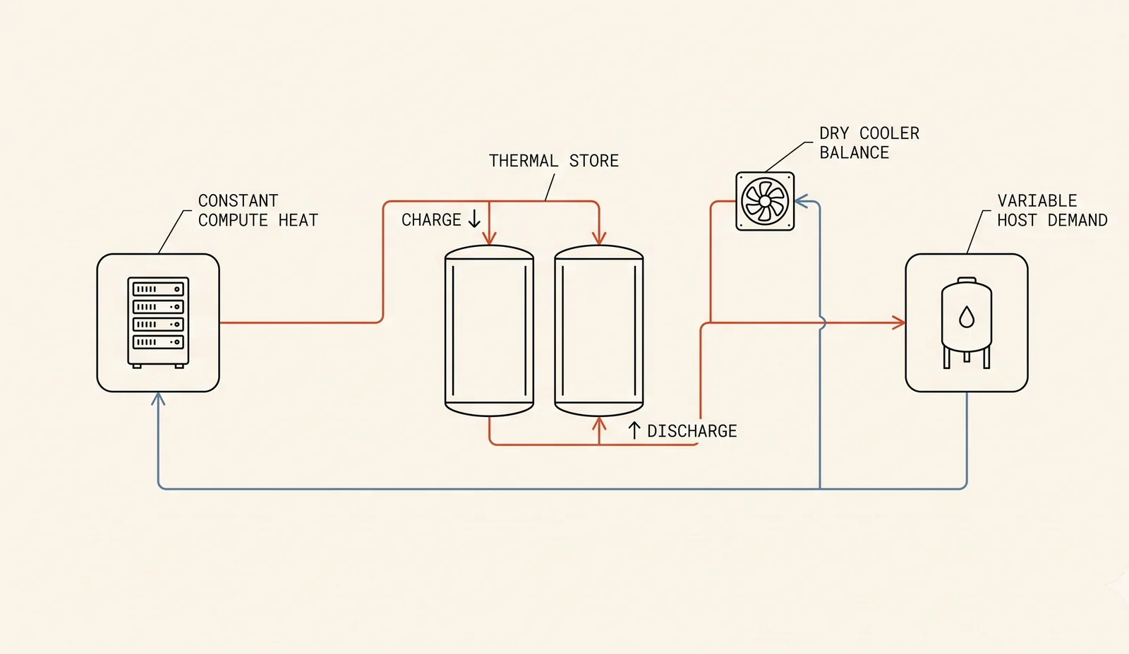
Buffering and demand matching between a constant compute heat source and a variable industrial heat user, so compute never waits on thermal demand.

Solution detail
RC 05

Process integration kits

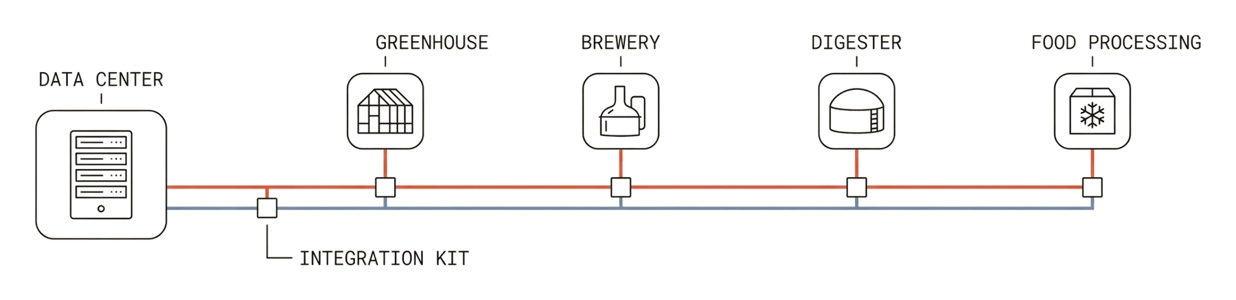
Integration engineered per host industry: district networks, digesters, brewery hot water and cleaning, pasteurisation, greenhouse climate.

Solution detail
RC 06

Loop closure and by product return

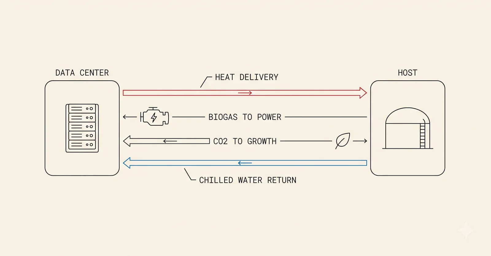
Host by products return to the data center as supplementary resource: biogas to power, CO2 to cooling or plant growth, chilled water to the cooling system.

Solution detail

Generation

GN 01

800 V DC distribution

Direct current from generation and storage to the rack. Conversion stages removed, copper cut, and the architecture the next accelerator generation will demand.

Solution detail
GN 02

Generation and storage coupling

On site generation and storage dispatched against compute load and heat demand as one problem, under one control scheme.

Solution detail
GN 03

Grid aware operation

Curtailment capture, demand response and constrained grid operation, so compute lands in markets where new utility load waits years.

Solution detail
GN 04

Waste to energy integration

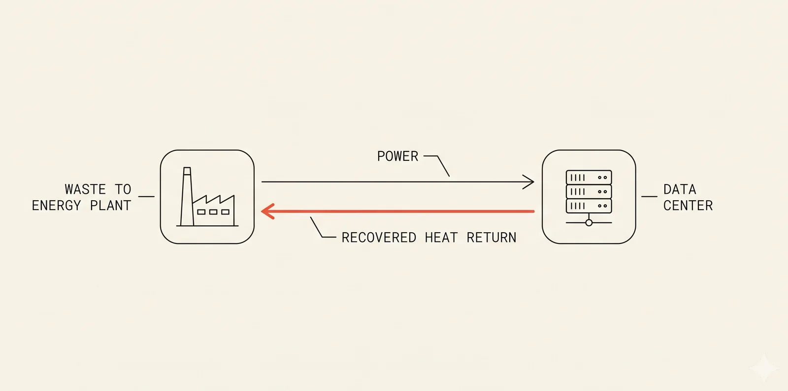
Compute taking the electrons from upgraded waste to energy facilities, with recovered heat returned to the process.

Solution detail
GN 05

Solar and storage at the interconnection

On site solar and battery storage sharing the point of interconnection with compute, dispatched by the same controller.

Solution detail
GN 06

Gas and biogas generation

Dispatchable on site generation, including host biogas, with engine heat recovered alongside compute heat.

Solution detail

Optimisation

OP 01

Edge Gateway

Placeholder description. On site control, safety interlocks and telemetry at block and pod level. The layer that makes unstaffed operation of a 50 kW site possible.

Solution detail
OP 02

Mesh AI

Placeholder description. Site level co optimisation of compute load, cooling, heat delivery and the dry cooler path, hour by hour.

Solution detail
OP 03

Node Intelligence

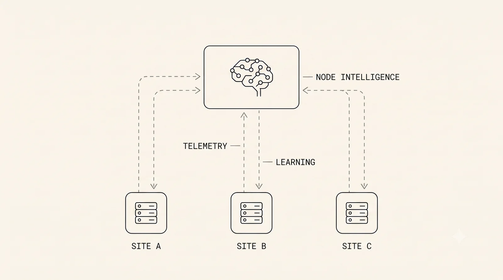
Placeholder description. Fleet analytics: cross fleet learning, predictive maintenance and benchmarking across every MicroLink deployment.

Solution detail
OP 04

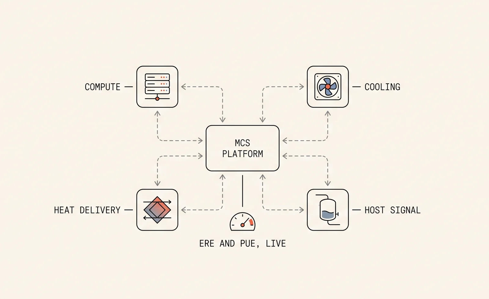
MCS platform

The management and control platform tying the suite together, named in the ML-IND-001 filing as the adaptive controller balancing IT load, thermal export and host demand signal in real time.

Solution detail
OP 05

Workload and thermal scheduling

Compute placement and scheduling against heat demand, power price and grid signals, so the same rack earns in three markets.

Solution detail
OP 06

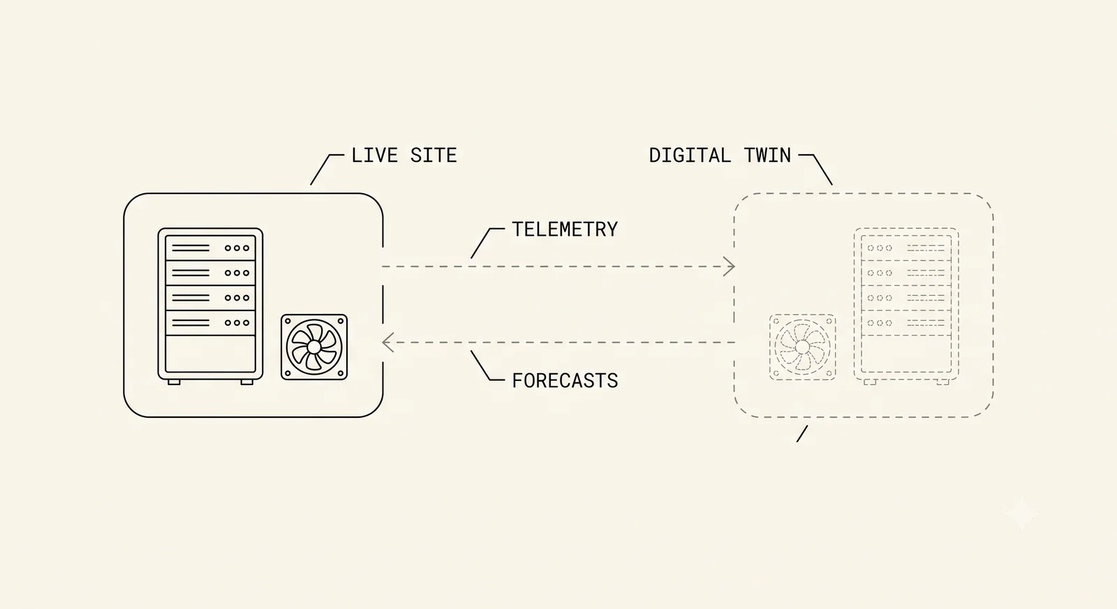
Digital twin and forecasting

Site models and forecasting for industrial thermal demand, weather, price and grid state, feeding every dispatch decision.

Solution detail

RC 01 Solution detail

Metered heat delivery interface

One metered exchanger between MicroLink plant and the host partner's systems: process hot water, digesters, district heat, greenhouses. The commercial and physical boundary in a single engineered product.

What is new here

  • A standard, meterable boundary product for delivered heat where the industry has ad hoc engineering
  • Heat accounting built for ERE reporting alongside PUE from live metering
GRAPHIC PLACEHOLDER: Metered heat delivery interface concept diagram, supply and return colour coding, dry cooler path where relevant

Fig RC 01.1 Draft

IMAGE PLACEHOLDER: Metered heat delivery interface hardware or interface

Fig RC 01.2 Draft

IP position

Covered by the ML-IND-001 industrial symbiosis filing, patent pending. Detail on the overview.

All solutions

RC 02 Solution detail

High grade return water

Direct to chip liquid cooling engineered from the first decision for recovery, returning water at 40 to 65°C (104 to 149°F) matched to real industrial demand.

What is new here

  • Cooling designed backwards from the heat user's temperature requirement, not forwards from the chip
  • Dry coolers sized for the full load carry whatever the host partner does not take, hour by hour
GRAPHIC PLACEHOLDER: High grade return water concept diagram, supply and return colour coding, dry cooler path where relevant

Fig RC 02.1 Draft

IMAGE PLACEHOLDER: High grade return water hardware or interface

Fig RC 02.2 Draft

IP position

Placeholder. Candidate protection route, related filings and trade secret scope for high grade return water. Summary on the overview.

All solutions

RC 03 Solution detail

Heat pump temperature boosting

Conditioning stage heat pumps lift return water to the temperature the host process actually needs, from digester duty at 35 to 55°C (95 to 131°F) up to cleaning and pasteurisation duty at 60 to 90°C (140 to 194°F).

What is new here

  • Heat pump integration sized against a live compute heat source rather than ambient
  • Temperature upgrade selected per host process, not per industry rule of thumb
GRAPHIC PLACEHOLDER: Heat pump temperature boosting concept diagram, supply and return colour coding, dry cooler path where relevant

Fig RC 03.1 Draft

IMAGE PLACEHOLDER: Heat pump temperature boosting hardware or interface

Fig RC 03.2 Draft

IP position

Placeholder. Candidate protection route, related filings and trade secret scope for heat pump temperature boosting. Summary on the overview.

All solutions

RC 04 Solution detail

Demand matching and storage

Buffering and demand matching between a constant compute heat source and a variable industrial heat user, so compute never waits on thermal demand.

What is new here

  • Placeholder: storage sizing method, demand forecasting for industrial thermal loads
  • Placeholder: charge and discharge control against host process schedules
GRAPHIC PLACEHOLDER: Demand matching and storage concept diagram, supply and return colour coding, dry cooler path where relevant

Fig RC 04.1 Draft

IMAGE PLACEHOLDER: Demand matching and storage hardware or interface

Fig RC 04.2 Draft

IP position

Placeholder. Candidate protection route, related filings and trade secret scope for demand matching and storage. Summary on the overview.

All solutions

RC 05 Solution detail

Process integration kits

Integration engineered per host industry: district networks, digesters, brewery hot water and cleaning, pasteurisation, greenhouse climate.

What is new here

  • An embodiment library spanning wastewater treatment, brewing, controlled environment agriculture and food processing
  • One architecture proven across four host process families
GRAPHIC PLACEHOLDER: Process integration kits concept diagram, supply and return colour coding, dry cooler path where relevant

Fig RC 05.1 Draft

IMAGE PLACEHOLDER: Process integration kits hardware or interface

Fig RC 05.2 Draft

IP position

Placeholder. Candidate protection route, related filings and trade secret scope for process integration kits. Summary on the overview.

All solutions

RC 06 Solution detail

Loop closure and by product return

Host by products return to the data center as supplementary resource: biogas to power, CO2 to cooling or plant growth, chilled water to the cooling system.

What is new here

  • Closed loop energy cycling between compute and host, metered in both directions
  • By product paths designed into the system architecture from the first line
GRAPHIC PLACEHOLDER: Loop closure and by product return concept diagram, supply and return colour coding, dry cooler path where relevant

Fig RC 06.1 Draft

IMAGE PLACEHOLDER: Loop closure and by product return hardware or interface

Fig RC 06.2 Draft

IP position

Covered by the ML-IND-001 industrial symbiosis filing, patent pending. Detail on the overview.

All solutions

GN 01 Solution detail

800 V DC distribution

Direct current from generation and storage to the rack. Conversion stages removed, copper cut, and the architecture the next accelerator generation will demand.

What is new here

  • An 800 V DC bus designed as native distribution for a containerised pod, not a lab demonstration
  • Protection and safety philosophy for high voltage DC inside industrial host partner facilities
GRAPHIC PLACEHOLDER: 800 V DC distribution concept diagram, supply and return colour coding, dry cooler path where relevant

Fig GN 01.1 Draft

IMAGE PLACEHOLDER: 800 V DC distribution hardware or interface

Fig GN 01.2 Draft

IP position

Placeholder. Candidate protection route, related filings and trade secret scope for 800 v dc distribution. Summary on the overview.

All solutions

GN 02 Solution detail

Generation and storage coupling

On site generation and storage dispatched against compute load and heat demand as one problem, under one control scheme.

What is new here

  • Nobody dispatches compute, generation and recovered heat together. That co optimisation is the programme
  • Placeholder: asset classes in scope
GRAPHIC PLACEHOLDER: Generation and storage coupling concept diagram, supply and return colour coding, dry cooler path where relevant

Fig GN 02.1 Draft

IMAGE PLACEHOLDER: Generation and storage coupling hardware or interface

Fig GN 02.2 Draft

IP position

Placeholder. Candidate protection route, related filings and trade secret scope for generation and storage coupling. Summary on the overview.

All solutions

GN 03 Solution detail

Grid aware operation

Curtailment capture, demand response and constrained grid operation, so compute lands in markets where new utility load waits years.

What is new here

  • Placeholder: grid services scope
  • Placeholder: interconnection strategy method
GRAPHIC PLACEHOLDER: Grid aware operation concept diagram, supply and return colour coding, dry cooler path where relevant

Fig GN 03.1 Draft

IMAGE PLACEHOLDER: Grid aware operation hardware or interface

Fig GN 03.2 Draft

IP position

Placeholder. Candidate protection route, related filings and trade secret scope for grid aware operation. Summary on the overview.

All solutions

GN 04 Solution detail

Waste to energy integration

Compute taking the electrons from upgraded waste to energy facilities, with recovered heat returned to the process.

What is new here

  • Placeholder: facility upgrade model and offtake structure
  • Placeholder: firm baseload pairing with compute load
GRAPHIC PLACEHOLDER: Waste to energy integration concept diagram, supply and return colour coding, dry cooler path where relevant

Fig GN 04.1 Draft

IMAGE PLACEHOLDER: Waste to energy integration hardware or interface

Fig GN 04.2 Draft

IP position

Placeholder. Candidate protection route, related filings and trade secret scope for waste to energy integration. Summary on the overview.

All solutions

GN 05 Solution detail

Solar and storage at the interconnection

On site solar and battery storage sharing the point of interconnection with compute, dispatched by the same controller.

What is new here

  • Placeholder: shared POI sizing method
  • Placeholder: storage duty cycle against compute and heat demand
GRAPHIC PLACEHOLDER: Solar and storage at the interconnection concept diagram, supply and return colour coding, dry cooler path where relevant

Fig GN 05.1 Draft

IMAGE PLACEHOLDER: Solar and storage at the interconnection hardware or interface

Fig GN 05.2 Draft

IP position

Placeholder. Candidate protection route, related filings and trade secret scope for solar and storage at the interconnection. Summary on the overview.

All solutions

GN 06 Solution detail

Gas and biogas generation

Dispatchable on site generation, including host biogas, with engine heat recovered alongside compute heat.

What is new here

  • Placeholder: biogas conditioning and engine integration
  • Placeholder: combined heat accounting across engine and compute sources
GRAPHIC PLACEHOLDER: Gas and biogas generation concept diagram, supply and return colour coding, dry cooler path where relevant

Fig GN 06.1 Draft

IMAGE PLACEHOLDER: Gas and biogas generation hardware or interface

Fig GN 06.2 Draft

IP position

Placeholder. Candidate protection route, related filings and trade secret scope for gas and biogas generation. Summary on the overview.

All solutions

OP 01 Solution detail

Edge Gateway

Placeholder description. On site control, safety interlocks and telemetry at block and pod level. The layer that makes unstaffed operation of a 50 kW site possible.

What is new here

  • Lights out operation at the smallest useful scale, driven by software rather than site staff
  • Same telemetry model from 50 kW to 1 GW
GRAPHIC PLACEHOLDER: Edge Gateway concept diagram, supply and return colour coding, dry cooler path where relevant

Fig OP 01.1 Draft

IMAGE PLACEHOLDER: Edge Gateway hardware or interface

Fig OP 01.2 Draft

IP position

Placeholder. Candidate protection route, related filings and trade secret scope for edge gateway. Summary on the overview.

All solutions

OP 02 Solution detail

Mesh AI

Placeholder description. Site level co optimisation of compute load, cooling, heat delivery and the dry cooler path, hour by hour.

What is new here

  • Heat delivery to the host partner as a first class control objective alongside uptime
  • Placeholder: optimisation scope and method
GRAPHIC PLACEHOLDER: Mesh AI concept diagram, supply and return colour coding, dry cooler path where relevant

Fig OP 02.1 Draft

IMAGE PLACEHOLDER: Mesh AI hardware or interface

Fig OP 02.2 Draft

IP position

Placeholder. Candidate protection route, related filings and trade secret scope for mesh ai. Summary on the overview.

All solutions

OP 03 Solution detail

Node Intelligence

Placeholder description. Fleet analytics: cross fleet learning, predictive maintenance and benchmarking across every MicroLink deployment.

What is new here

  • A telemetry and data model that turns every site into training data for the next
  • Placeholder: analytics scope
GRAPHIC PLACEHOLDER: Node Intelligence concept diagram, supply and return colour coding, dry cooler path where relevant

Fig OP 03.1 Draft

IMAGE PLACEHOLDER: Node Intelligence hardware or interface

Fig OP 03.2 Draft

IP position

Placeholder. Candidate protection route, related filings and trade secret scope for node intelligence. Summary on the overview.

All solutions

OP 04 Solution detail

MCS platform

The management and control platform tying the suite together, named in the ML-IND-001 filing as the adaptive controller balancing IT load, thermal export and host demand signal in real time.

What is new here

  • ERE reported alongside PUE as a live operational metric at every site
  • The control layer of a filed patent architecture, not a roadmap item
GRAPHIC PLACEHOLDER: MCS platform concept diagram, supply and return colour coding, dry cooler path where relevant

Fig OP 04.1 Draft

IMAGE PLACEHOLDER: MCS platform hardware or interface

Fig OP 04.2 Draft

IP position

Placeholder. Candidate protection route, related filings and trade secret scope for mcs platform. Summary on the overview.

All solutions

OP 05 Solution detail

Workload and thermal scheduling

Compute placement and scheduling against heat demand, power price and grid signals, so the same rack earns in three markets.

What is new here

  • Heat demand as a scheduling input alongside latency and price
  • Placeholder: scheduling method and constraints
GRAPHIC PLACEHOLDER: Workload and thermal scheduling concept diagram, supply and return colour coding, dry cooler path where relevant

Fig OP 05.1 Draft

IMAGE PLACEHOLDER: Workload and thermal scheduling hardware or interface

Fig OP 05.2 Draft

IP position

Placeholder. Candidate protection route, related filings and trade secret scope for workload and thermal scheduling. Summary on the overview.

All solutions

OP 06 Solution detail

Digital twin and forecasting

Site models and forecasting for industrial thermal demand, weather, price and grid state, feeding every dispatch decision.

What is new here

  • Placeholder: model scope per host industry
  • Placeholder: forecast horizon and accuracy targets
GRAPHIC PLACEHOLDER: Digital twin and forecasting concept diagram, supply and return colour coding, dry cooler path where relevant

Fig OP 06.1 Draft

IMAGE PLACEHOLDER: Digital twin and forecasting hardware or interface

Fig OP 06.2 Draft

IP position

Placeholder. Candidate protection route, related filings and trade secret scope for digital twin and forecasting. Summary on the overview.

All solutions

Projects Where the technology is proven

Development projects

Twelve sites across the portfolio. Each card shows what the site is, its stage, and the technologies it proves, mapped to the register on the solutions page.

Franklin Twp, Richland Co, OH

Mansfield

250+ MW IT · Owned · Pre construction

Ground up campus on owned land. Proves the full campus stack: pod repetition, on site generation dispatch and campus scale DC distribution.

GN 01 800 V DC
GN 02 Generation coupling
OP 02 Mesh AI
OP 04 MCS platform
RC 01 Metered heat delivery

Arizona

Gigawatt Land

250+ MW IT · Owned · Site identified

Ground up campus with solar, storage and gas at the same point of interconnection. The proving ground for generation and storage coupling at full scale.

GN 01 800 V DC
GN 02 Generation coupling
GN 03 Grid aware operation
OP 04 MCS platform

Pennsylvania

Fort Cherry District

250+ MW IT · Owned · Site identified

Ground up district development in early diligence. Proves campus master planning and grid aware operation on a constrained interconnection.

GN 01 800 V DC
GN 02 Generation coupling
GN 03 Grid aware operation
OP 02 Mesh AI

Northampton County, PA

Bethlehem

8 MW IT · Owned · Pre construction

Smaller owned build. First full test of the pod as the unit of repetition with heat delivery engineered in from day one.

RC 01 Metered heat delivery
RC 02 High grade return water
OP 01 Edge Gateway
OP 02 Mesh AI

Massena, NY

Massena St Lawrence

250+ MW IT · Owned · Site identified

Deliberately the hardest environment in the New York programme. Proves winter operation, grid aware dispatch and the co optimisation stack under real constraint.

GN 02 Generation coupling
GN 03 Grid aware operation
OP 02 Mesh AI
OP 04 MCS platform

Chicago, IL

Stickney MWRD

45 MW IT · Host · LOI in place

Compute inside one of the largest wastewater treatment plants in the world, heat delivered to process. The reference case for the metered heat interface at scale.

RC 01 Metered heat delivery
RC 02 High grade return water
RC 04 Demand matching and storage
OP 02 Mesh AI

New York

NYSERDA pilot

45 MW IT · Host · Confirmed interest

Pilot developed with New York State support. Proves the host partner model and live ERE reporting alongside PUE for a public counterpart.

RC 01 Metered heat delivery
RC 02 High grade return water
OP 02 Mesh AI
GN 03 Grid aware operation

Japan

Undisclosed

45 MW IT · Host · Confirmed interest

Host partner deployment in Japan, name withheld. Proves the stack in a second regulatory and grid environment.

RC 01 Metered heat delivery
RC 02 High grade return water
OP 02 Mesh AI

Philadelphia, PA

Grays Ferry

25 MW IT · Host · LOI in place

Deployment at a district energy site. Proves delivery of recovered heat into a live district network and thermal demand matching.

RC 01 Metered heat delivery
RC 02 High grade return water
RC 04 Demand matching and storage
GN 03 Grid aware operation

New York, NY

Newtown Creek

15 MW IT · Host · LOI in place

Compute at a wastewater treatment site in New York City, heat to digesters. Proves the edge and pod stack inside dense urban infrastructure.

RC 01 Metered heat delivery
RC 02 High grade return water
OP 01 Edge Gateway
OP 02 Mesh AI

San Jose, CA

San Jose

15 MW IT · Host · Confirmed interest

Host partner site in the Bay Area. Proves unstaffed operation under Edge Gateway close to compute demand.

RC 01 Metered heat delivery
RC 02 High grade return water
OP 01 Edge Gateway

New Jersey

Princeton

4 MW IT · Host · Site identified

Small host deployment feeding a district heating opportunity. Proves the 50 kW to pod transition on one control stack.

RC 01 Metered heat delivery
RC 02 High grade return water
OP 01 Edge Gateway

DRAFT. Technology mappings per site are placeholders for internal review. Confirm what is disclosed to funds before circulation.

Reference Partners, technologies, research

What we build on

The manufacturers we standardise with, the technologies we work with, and the research behind the programme.

Partners

MANUFACTURING

Vertiv

Cooling distribution, CDUs, dry coolers and power modules standardised against MicroLink reference designs. Placeholder detail.

MANUFACTURING

Leading manufacturers

Placeholder blocks for additional named manufacturing and component partners.

HOST PARTNERS

Industrial and district energy

Placeholder: the host partner categories and named partners cleared for disclosure.

GRAPHIC PLACEHOLDER: partner logo band, pending permissions

Technologies we work with

  • Direct to chip liquid cooling, returning water at 40 to 65°C (104 to 149°F)
  • Dry coolers sized for the full load, carrying whatever the host partner does not take
  • Coolant distribution units and secondary loop plant from leading manufacturers
  • 800 V DC power conversion and protection components
  • On site generation and storage: placeholder asset classes
  • Placeholder: accelerator and IT platform references

Research to date

ReferenceTopicWithStatus
R1Heat recovery performance, placeholder topicUniversity research collaborationPlaceholder
R2Co dispatch of compute, generation and heatInternalPlaceholder
R3800 V DC distribution studyPlaceholder partnerPlaceholder

DRAFT. Add published papers, white papers, bases of design and field data references here.